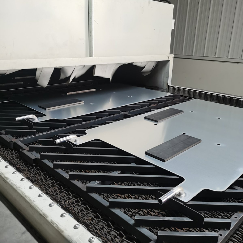
Core Technical Directive: Achieving peak operational efficiency and extended service life in a brazing furnace mesh belt requires balancing three unyielding variables: structural alloy chemistry, thermodynamic load profile, and mechanical drive synchronization. Selecting an alloy with a minimum nickel-chromium ratio of 35/19 or utilizing specialized nickel-base superalloys for processes exceeding 1000°C is mandatory to suppress devastating microstructural failures like grain boundary cavitation and green rot expansion.
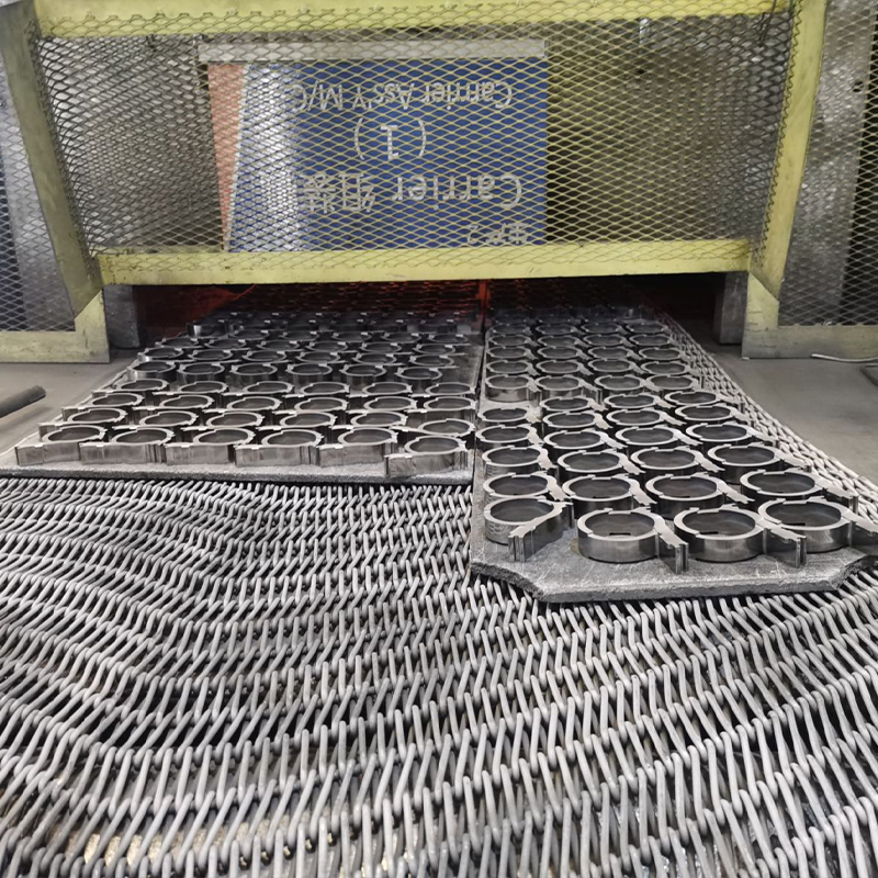
Controlled atmosphere brazing (CAB) and high-vacuum thermal joining demand absolute precision from structural material transportation systems. When traveling through preheat zones, flux activation stages, alloy melting steps, and forced-cooling cells, the continuous wire mesh belt bears the combined burden of high mechanical tensile forces and severe thermal gradients. Understanding the engineering parameters that govern high-temperature mesh belt wear, deformation mechanisms, and structural lifecycle management directly enables high-throughput industrial operations to avoid unexpected production stoppages and lower overall lifecycle operating costs.
Metallurgical Foundations of High-Temperature Mesh Materials
Selecting the fundamental alloy composition determines the foundational mechanical limitations of a brazing furnace mesh belt. In systems operating between 600°C and 1150°C, typical base metals rapidly undergo atomic crystal lattice transformations that diminish mechanical load capacities. High-temperature mesh engineering relies entirely on specialized iron-nickel-chromium or nickel-base superalloys engineered to resist microscopic grain slip and macroscopic physical deformation.
Chromium forms the bedrock of oxidation defense. When exposed to an environment containing oxygen or trace water moisture at elevated temperatures, chromium instantly migrates to the outer boundaries of the wire, forming an impermeable, microscopic chromium oxide (Cr₂O₃) layer. This oxide barrier isolates the underlying metal matrix from further chemical oxidation. For continuous thermal profiling above 950°C, the chromium content must exceed 18% by weight to ensure that this protective barrier remains self-healing when mechanical wear or structural stretching creates microscopic surface cracks.
Nickel works synergistically with chromium to transform the basic body-centered cubic (BCC) ferrite structure of standard iron into a highly stable face-centered cubic (FCC) austenite structure. This austenitic matrix provides a much higher resistance to plastic deformation over long exposure periods. Furthermore, high nickel concentrations shield the belt from destructive carburization and nitriding reactions caused by organic lubricants or specific protective atmospheres injected during copper or silver brazing steps.
| Alloy Designation |
Nickel (Ni) % |
Chromium (Cr) % |
Silicon (Si) % |
Maximum Stable Temp (°C) |
| AISI 314 |
19.0 - 22.0 |
23.0 - 26.0 |
1.5 - 3.0 |
1000°C |
| Alloy 601 |
58.0 - 63.0 |
21.0 - 25.0 |
0.5 Max |
1150°C |
| Alloy 800HT |
30.0 - 35.0 |
19.0 - 23.0 |
1.0 Max |
1100°C |
| AISI 310S |
19.0 - 22.0 |
24.0 - 26.0 |
1.5 Max |
1035°C |
Mechanisms of High-Temperature Creep and Deformation
Creep is the slow, continuous plastic deformation that takes place when a wire mesh belt operates under a constant mechanical load at temperatures above 40% of its absolute melting point. In continuous brazing furnaces, the mesh belt is subject to constant tension from the drive rollers while carrying dense automotive heat exchangers, electronics enclosures, or industrial plumbing assemblies. Over thousands of operational hours, this stress causes structural voids to open along internal grain boundaries.
Creep progression moves through three distinct phases: primary, secondary, and tertiary deformation. During the primary stage, the metal undergoes initial strain hardening. The secondary phase represents a long, linear steady-state where the rate of deformation remains constant. It is within this secondary window that engineers must manage the belt's usable lifetime. Once tertiary creep begins, micro-cracks coalesce into catastrophic macroscopic fractures along the wire structure, causing the belt to snap unexpectedly under nominal operational tension.
Dislocation Climb Creep
At highly elevated temperatures, structural dislocations within the metal crystal lattice gain enough thermal energy to bypass obstacles like impurities or precipitates. Atomic vacancies diffuse through the crystal, allowing the metal planes to slide past one another, causing permanent, incremental belt elongation.
Grain Boundary Sliding
Individual microscopic grains within the wire matrix begin to shift independently along their boundary planes. If the alloy lacks stabilizing element precipitates like titanium, aluminum, or niobium, these grain boundaries slide past each other easily, accelerating belt distortion and structural width narrowing.
Weave Configurations and Geometric Selection Rules
The geometric layout of the woven wires plays an equal role alongside material chemistry in determining a brazing furnace mesh belt’s physical capabilities. Standard weaves cannot handle the directional stresses of heavy-load brazing operations. Industrial operations must match the weave geometry to the precise thermal and structural needs of their product components.
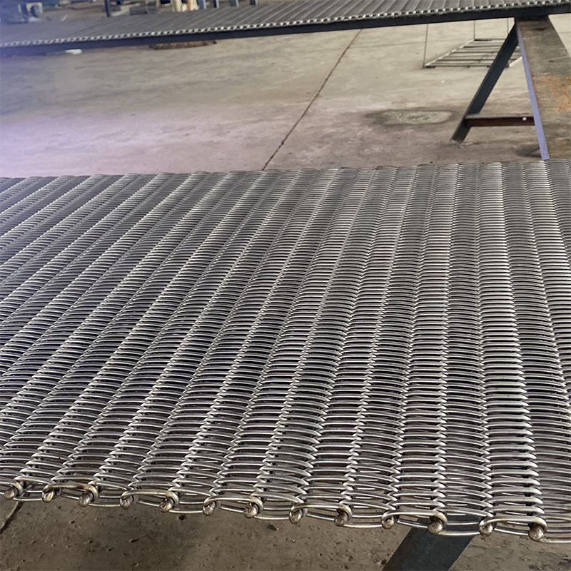
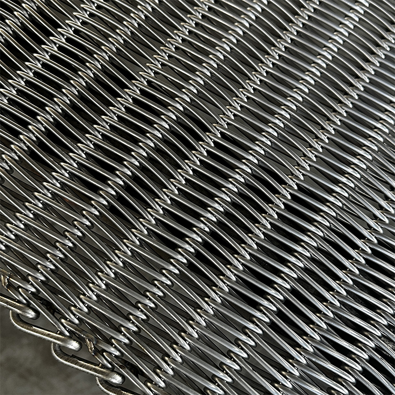
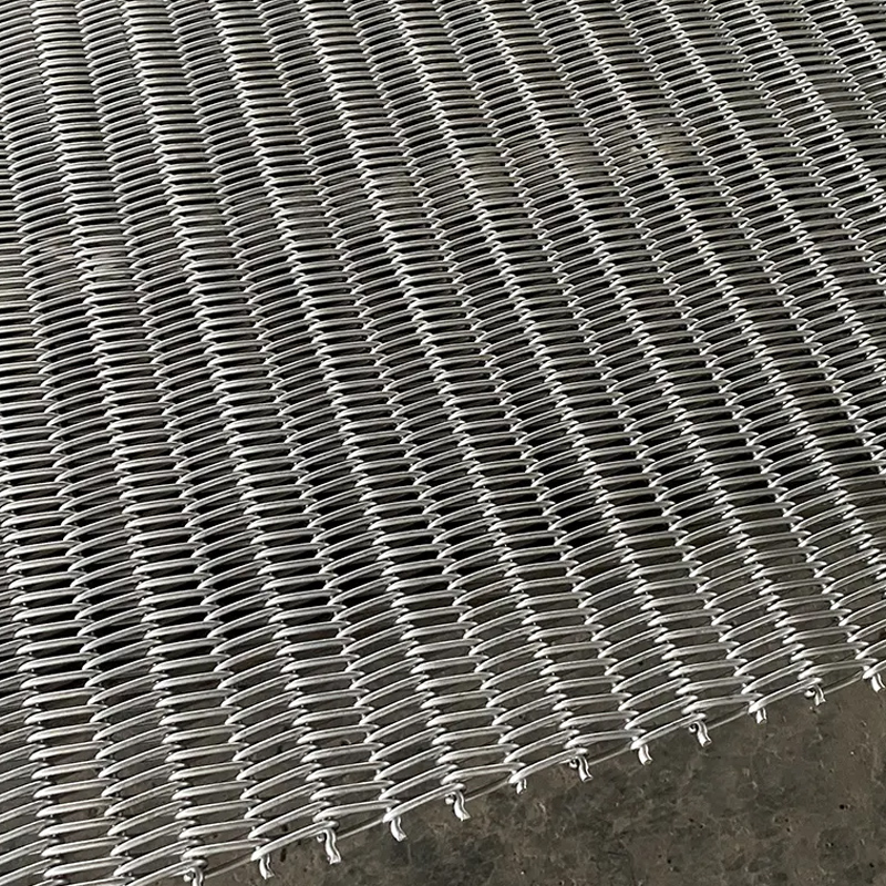
The most widely implemented configuration for high-yield brazing lines is the balanced weave design. A balanced weave consists of alternating left-hand and right-hand spirals joined by straight or crimped connecting rods. This alternating geometry completely neutralizes the natural tendency of a single-directional spiral belt to track sideways against the furnace walls. By counter-balancing the rotational torque forces internally, the belt travels perfectly straight under varying tension conditions.
Compound balanced weaves add multiple compressed spirals and cross-rods into a dense, nested assembly. This produces a flat, closed surface that provides dense support for small parts while offering a thick thermal mass. While compound weaves prevent tiny components or brazing preforms from tilting or falling through the mesh openings, they demand significantly more energy to heat up and cool down, altering the thermal profile requirements of the overall furnace system.
- Standard Balanced Weave: Alternating directional spirals linked by crimped rods. Provides excellent gas circulation, rapid thermal equalization, and dependable tracking for generic heat-treating lines.
- Double Balanced Weave: Features interlocking pairs of spirals to increase tensile strength and load capabilities without requiring thicker wire gauges that reduce belt flexibility.
- Compound Balanced Weave (Cord Weave): Extremely tight, dense configuration with nested wires. Ideal for small medical components or electronic pins, but possesses higher thermal inertia.
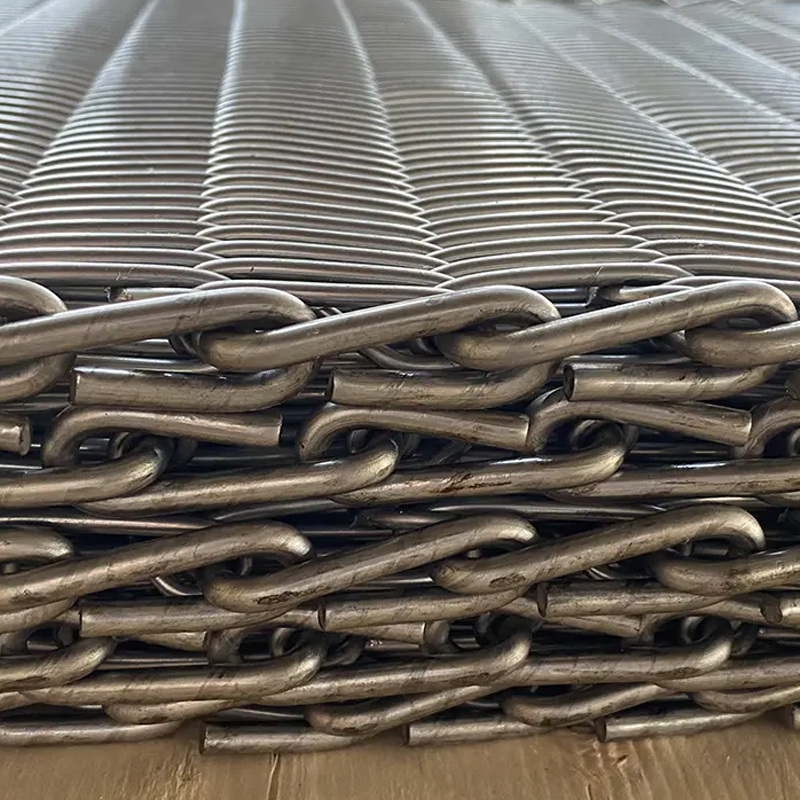
- Rod Reinforced Weave: Straight reinforcement rods are inserted through the spiral intersections to increase resistance to high-temperature stretching, allowing higher weight loads per square meter.
Atmospheric Interactions and Chemical Degradation Pathologies
Brazing furnace mesh belts do not operate in isolated vacuums; they interact continuously with precise gaseous processing environments. Controlled atmosphere brazing frequently relies on nitrogen, cracked ammonia (hydrogen-nitrogen blends), exothermic gas, or high-purity hydrogen to remove surface oxides from the parts being joined. These gas chemical compositions can trigger aggressive deterioration mechanisms if they are not monitored carefully.
Green rot is a destructive condition that affects high-nickel-chromium alloys when they operate in low-oxygen, reducing atmospheres containing carbon or nitrogen. If trace oxygen is present alongside carbon, chromium reacts internally to form chromium carbides along grain boundaries instead of forming a helpful, protective surface oxide layer. This leaves behind a green-tinged, chromium-depleted nickel matrix that lacks mechanical strength. The wire mesh becomes highly brittle and can crumble under light mechanical loads.
Carburization represents an alternative degradation vector. In copper brazing lines where parts may have traces of stamping oils, the high furnace heat cracks these hydrocarbons, liberating free carbon atoms. These atoms diffuse directly into the hot wire mesh belt, binding with internal alloying elements to form hard, brittle carbides. This carbide network reduces the wire's ductility, making it susceptible to sudden fatigue cracking when cycling through the cooler regions of the processing line.
Thermal Fatigue from Cyclic Heating and Cooling Processes
While continuous furnaces strive to maintain steady temperatures, the mesh belt itself experiences aggressive cyclic thermal loading. As a specific segment of the belt moves out of the 1050°C brazing zone and enters the forced-cooling or water-jacketed cooling sections, it experiences severe localized temperature drops. This cyclic expansion and contraction generates internal thermal stresses that can exceed the material's yield strength.
The core mechanism of thermal fatigue involves localized micro-strains. The exterior surface of a wire cools and contracts much faster than its interior core. This creates strong tension forces on the outer skin of the wire, while the inner core experiences compressive forces. Over hundreds of round trips through the furnace loop, these opposing cyclic stresses trigger microscopic cracks that start on the surface and migrate inward until the wire completely breaks.
To reduce thermal fatigue damage, furnace conveyor designs must avoid abrupt, unshielded cooling transitions. Incorporating insulated transition zones between the main heating chamber and the rapid cooling jets lowers the thermal shock rate. Choosing alloys with low thermal expansion coefficients and high thermal conductivity helps equalize internal wire temperatures quickly, safely dampening internal micro-strain forces.
Drive Engineering and Mechanical Tension Optimization
Even the highest-grade superalloy mesh belt will fail prematurely if the mechanical drive system is incorrectly engineered or out of alignment. The primary goal of drive engineering is to maintain the lowest possible operational tension required to smoothly move the belt and its payload. Excessive tension directly accelerates creep rates, rapidly shortening the operational lifespan of the assembly.
Friction drive systems utilize large, rubber-lagged or precision-machined steel drums to move the belt via surface friction. These setups require a precise balance between the slack-side counterweight tension and the drive-side pulling force. If the counterweight is too light, the drive drum slips, causing intense friction heating and localized abrasive wear on the mesh. If the counterweight is too heavy, the base tension rises across the entire furnace loop, pushing the wire mesh belt closer to its tertiary creep limit.
Positive drive systems use specialized sprockets that directly engage with reinforced chain edges attached to the sides of the mesh belt. This design completely eliminates friction slippage and allows for wide belt configurations under heavy weight loads. However, if the chain tracks on the left and right sides become slightly misaligned due to uneven thermal expansion inside the furnace, the cross-rods will twist and skew, causing severe mechanical binding and structural tearing along the edges of the belt.
Practical Life-Extension and Predictive Maintenance Protocols
Extending the operational lifespan of a brazing furnace mesh belt requires a structured, multi-tiered maintenance strategy that replaces reactive crisis management with proactive, data-driven procedures. Because high-temperature wire damage accumulates continuously, regular tracking and physical inspections are vital to ensuring continuous production availability.
A fundamental maintenance practice involves tracking the cumulative elongation of the belt over time. Technicians should establish fixed baseline measurement points outside the furnace and record the total stretch during weekly shutdowns. A healthy belt exhibits a linear, predictable stretch rate during its secondary creep phase. A sharp, sudden increase in elongation indicates that the material has entered its tertiary creep stage, signaling that a replacement belt should be scheduled immediately to prevent a catastrophic failure during operation.
| Inspection Frequency |
Target Metric / Area |
Optimal Parameter / Condition |
Corrective Action on Deviation |
| Every Shift |
Belt Tracking & Alignment |
Centered within ±15mm of tracking limits |
Adjust counter-tension rollers or tracking guide pins |
| Weekly |
Cumulative Elongation Rate |
Less than 0.1% total length increase per week |
Verify internal furnace tension weights and drag forces |
| Monthly |
Wire Junction & Spiral Inspection |
Zero visible micro-cracking or localized necking |
Cut out damaged mesh section and splice with new wire matching the batch |
| Quarterly |
Atmospheric Dew Point |
Maintained between -40°C and -60°C |
Inspect furnace seals and purge gas supply lines for moisture leaks |
Splicing and repairing damaged sections represents an effective method to safely maximize total belt lifecycle usage. When a localized zone of the belt experiences damage from an accidental part drop or a localized flame impingement, cutting out the distorted spirals and weaving in a new, matching section of wire restores structural integrity. It is critical that the repair wire shares the exact metallurgical batch and wire diameter as the original belt. Mixing different alloy grades or wire sizes introduces uneven thermal expansion points, which can quickly trigger severe tracking problems and accelerated cracking under load.
References
ASM International Handbook Committee. (2020). ASM Handbook, Volume 1: Properties and Selection: Irons, Steels, and High-Performance Alloys. ASM International.
Reed, R. C. (2008). The Superalloys: Fundamentals and Applications. Cambridge University Press.
Lai, G. Y. (2007). High-Temperature Corrosion and Materials Applications. ASM International.
Schmid, S. R., & Kalpakjian, S. (2018). Manufacturing Engineering and Technology (8th Edition). Pearson.



 English
 русский
 عربى
عربى